Hacking the HMO1202 logic pod - part 1
The Rohde & Schwarz HMO1202
oscilloscope is one of my favorite workbench tools (it’s actually a rebranded oscilloscope from Hameg. R&S acquired Hameg in 2005). This scope is out of production already (I bought it in 2016), and it’s not nearly as cool as all the new fancy scopes with large touchscreens and other cool features, but it serves me well, and I can’t justify buying a new one. It replaced my old Tektronix TDS2012B, which was really showing its age - desperately low screen resolution (QVGA, i.e., 320x240), only 2.5K samples memory, no intensity mode (a.k.a. “digital phosphor”), to name just a few annoyances. Switching to the HMO1202 was a giant leap.
However, there is one thing that I regret - HMO1202 includes an 8-channel logic analyzer that I can’t use. It requires the HO3508 logic pod, which was ridiculously expensive back then and is out of production now as well. But how difficult would it be to design a simple, compatible logic pod?
What information is already available?
A quick search in the usual places reminded me of the EEVBlog videos I watched a few years ago:
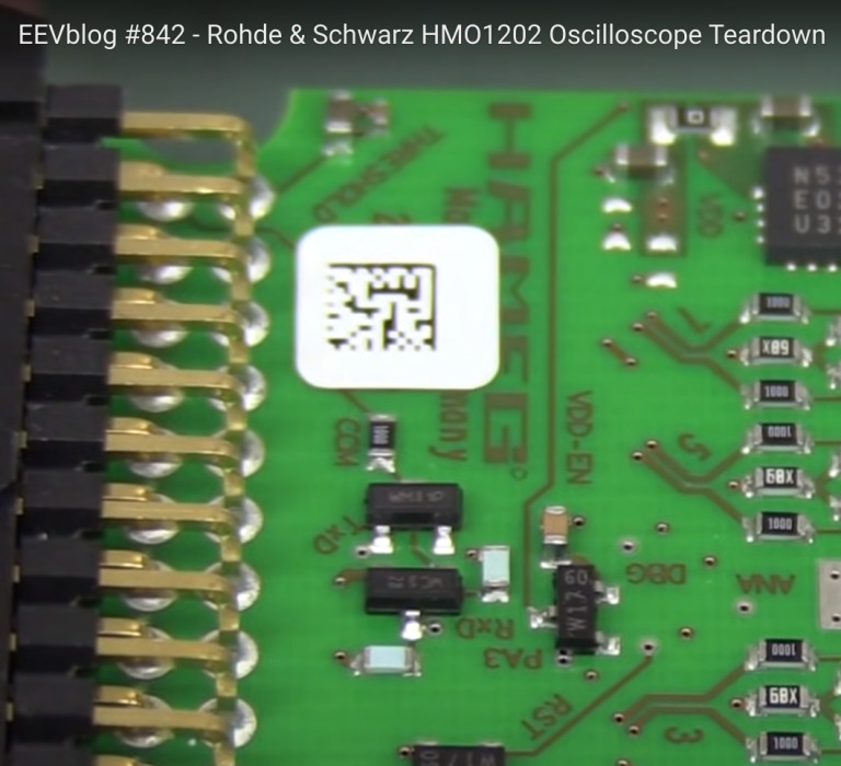
- EEVblog #842 - Rohde & Schwarz HMO1202 Oscilloscope Teardown
- EEVblog #879 - R&S HMO1202 Scope Bandwidth Hack Investigation
The teardown video is invaluable as a source of information:
- at 19:42 , Dave talks about the scope’s logic analyzer port,
- teardown of the actual logic probe begins at 40:33 .
We can infer a few facts from the video right away:
-
The pod utilizes Analog Devices ADCMP562 dual fast comparators with PECL differential outputs. Differential pairs are clearly visible on the scope PCB.
-
It uses EN5311QI DC-DC step-down converter (contrary to Dave’s assumption, it’s not an LDO, this chip has the inductor integrated) and LM2611 switching voltage inverter. I think it’s safe to assume that all the required voltages are derived from a single power supply line.
-
There’s a Zilog Z8F0123 microcontroller, but its role is unclear.
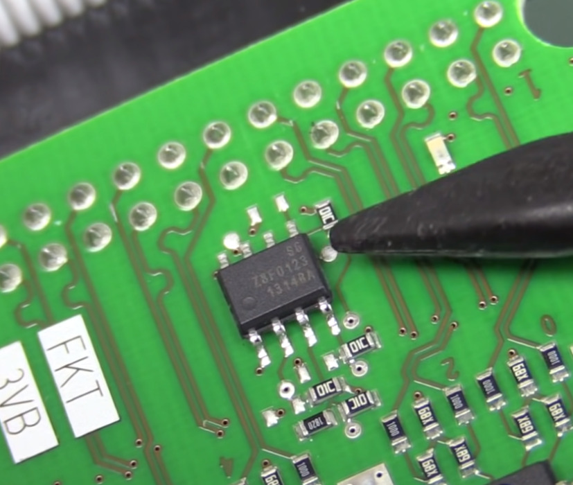
Pod MCU.
Also, I’ve found an interesting post on the EEVblog forum :
The short answer is yes, the HO3508 will work on the RTB. The longer answer is you have to be careful with the ZL03 (replacement for the HO3508) going to a Hameg and back to the RTB. If you run alignment on the HMO it will flash those alignment values to the ZL03. The RTB’s ZL03s are calibrated at the factory, so there is no alignment routine for them on the RTB and the ZL03 would need to be sent back in to be realigned.
TL;DR: HO3508 works on RTB. Don’t use ZL03 on HMO and run alignment and then bring it back to RTB. Best to keep your ZL03 with your RTBs.
Clearly:
-
Old
HO3508and newZL03pods use the same interface. Good to know I can purchaseZL03(it’s still a bit too expensive). -
There’s some non-volatile storage in the pod to store the calibration data. Most likely, it’s the Zilog’s MCU Flash memory (as it has no EEPROM).
-
Obviously, there must be some communication channel between the scope and pod (serial? 1-Wire perhaps?).
Initial pinout guesswork
Let’s check what we can deduce about the connector pinout. The pins used for each differential pair can be easily identified in the video snapshot below. The 6-pin SMD devices nearby are most likely for ESD protection.
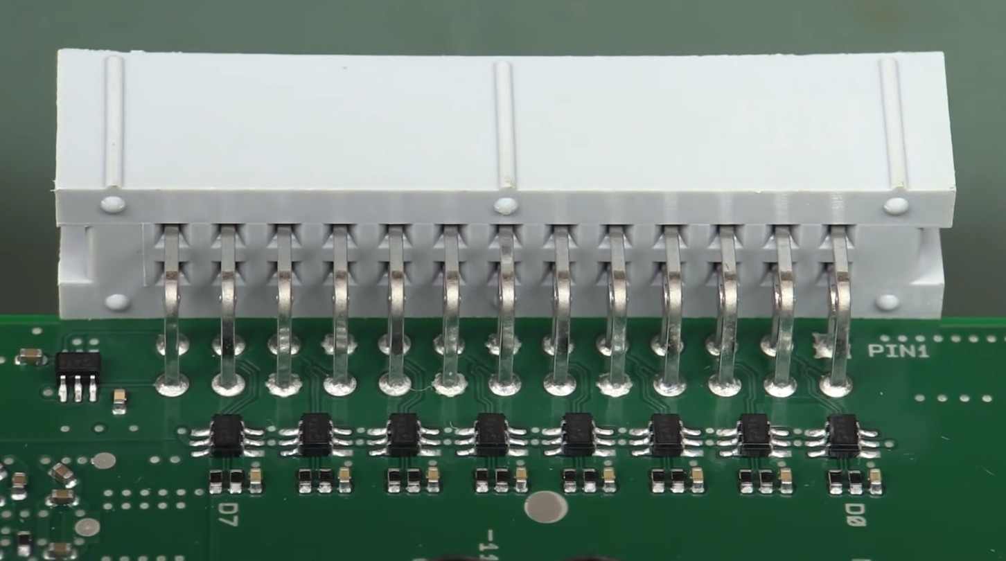
Pod receptacle - back view.
A low-voltage continuity tester helped to narrow down the GND pins - 1, 10, 13, 16, 19, 22.
Also, the scope allows for adjusting the logic level threshold voltage. Poking around with a multimeter, I found a signal at pin 25 - let’s call it VTH - which changes its voltage as the threshold is adjusted:
| Threshold setting | VTH voltage |
|---|---|
| 8V (max) | 1700 mV |
| 4V | 838 mV |
| 0V | -27 mV |
| -2V (min) | -460 mV |
On the pod PCB, there is a trace labeled COM, leading from pin 26 of the connector to some transistors with RxD and TxD labels nearby (by the way, there is a THRESHOLD label confirming previous guesswork, yay! I believe Dave was wrong about the MCU providing the threshold voltage).
COM trace and surrounding circuitry.
I guess that COM line is used for bi-directional communication using regular UART in half-duplex mode of some sort. At the scope, this line is pulled up to 3.3V (assuming that transmitters on both sides pull this line low).
Combining all the facts and guesses, we get the following preliminary pinout (gray pins are GND, differential pairs’ polarity doesn’t matter now):
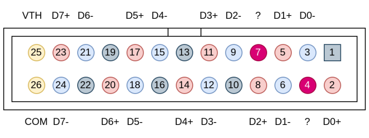
Preliminary pinout.
What next?
I have to admit I got stuck here. There are 2 pins (pin 4 and 7) of unknown purpose (measured a few hundred millivolts on both). Unfortunately, there are no visual hints on either of the PCBs, the traces are routed on the inner layers. Also, I have observed no activity on the COM pin whatsoever. I still hesitate to open my oscilloscope
I think the following assumptions are worth checking:
- either pin 4 or 7 is used to power the pod. It seems some conditions must be fulfilled before the power is enabled.
- it might be, that the second pin is used for hot-plug detection - might be that the scope tries to talk over
COMonly after plugging-in is detected. I will probably try pulling pins 4 and 7 low/high via a resistor and see if it changes anything. - it is also possible, that power is enabled only after some handshake over the
COMpin (typical MCU power consumption is very low, so it might be powered from theCOMline).
I’m still hesitating to dismantle my scope, as there’s still a warranty label on it (and it might not help much due to the PCB complexity). Gaining access to an original HO3508 (or ZL3) would be incredibly beneficial - the power pin could be easily identified by current measurement, the COM pin traffic could be sniffed, etc. Unfortunately, I have no access to one.
To be continued…
Edit 2023-10-30: Poking around, I’ve discovered that pins 4 and 7 are shorted together. I think it’s reasonable to assume that those pins deliver power to the pod (most likely 5V). That however, leaves no other pins for signaling the pod plug-in. Thus, I assume that power turns on after some negotiation over COM line (or power on pins 4 and 7 should be available all the time, and my scope is just damaged). It might be worth looking for UART registers in the firmware disassembly (this scope uses ATSAMA5D31
MPU).